Sensors &
Transmitter System
Transmitter System
Sensors
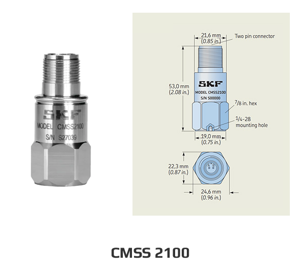
CMSS 2100
- Sensitivity : 100mV/g
- Acceleration range : 80g Peak
- Frequency range : 0.5Hz ~ 14,000Hz(±3dB)
- Power requirements : 18 to 30Vdc, 2 to 4mA
- Temperature range : -50℃ ~ 120℃
- Two mounting studs (1/4-28 and M8 × 1,25) provided
- Connections:
– Pin A: Signal/Power
– Pin B: Common - Weight: 90 g (3 2 oz )
- Case material: 316L stainless steel
1. General Purpose Sensors : CMSS 2100, CMSS 2200, CMSS 780C
2. Dual Sensors : CMSS 2100T, CMSS 2200T
3. Hazardous area approved Sensor : CMSS 786A-IS, CMSS 786A-D2
4. Hansford Sensor : HS-100(General Purpose Sensor), HS-173(Triax Sensor), etc
2. Dual Sensors : CMSS 2100T, CMSS 2200T
3. Hazardous area approved Sensor : CMSS 786A-IS, CMSS 786A-D2
4. Hansford Sensor : HS-100(General Purpose Sensor), HS-173(Triax Sensor), etc
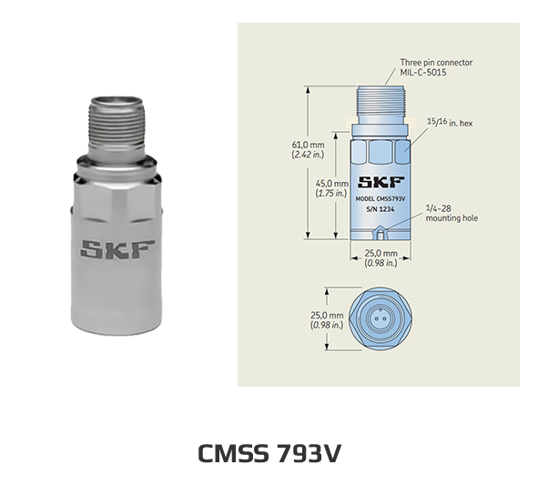
CMSS 793V
- Sensitivity : 100mV/g
- Acceleration range : 80g Peak
- Frequency range : 0.8Hz ~ 15,000Hz(±3dB)
- Power requirements : 18 to 30Vdc, 0.5 to 8mA
- Temperature range : -55℃ ~ 140℃
- Mounting: 1/4-28 tapped hole
- Connections:
– Pin A: Signal/Power
– Pin B: Common - Weight: 145 g (5 1 oz )
- Case material: 316L stainless steel
1. General Purpose Sensors : HS-100, HS-100S, HS-150
2. Dual Sensors : HS-150T, HS-150RT
3. Hazardous area approved Sensor : HS-100I, HS-100IS, HS-150I
4. Triax Sensor : HS-173
2. Dual Sensors : HS-150T, HS-150RT
3. Hazardous area approved Sensor : HS-100I, HS-100IS, HS-150I
4. Triax Sensor : HS-173
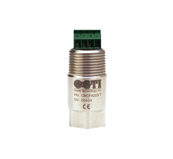
4~20mA Output Transmitter
CMCP 420VT Loop-Powered Vibration Velocity Transmitter
- Velocity and Dynamic(100mV/g) Output
- 4~20mA Output
- 2Hz ~ 2kHz Frequency Response
- Range : 0 ~ 25.4mm/s or 0 ~ 50.8mm/s
- Supply Voltage : 22 ~ 36Vdc
- Class I Division II Groups B-A Approved Standalone
CMCP 420VT-T Dual Parameter Loop-Powered
Vibration
and Temperature Transmitter
and Temperature Transmitter
- Two Loop Powered 4~20mA outputs
- Velocity RMS output & Temperature output
- 2Hz ~ 2kHz Frequency Response
- Range : 0 ~ 25.4mm/s or 0 ~ 50.8mm/s, 0~100℃
- Supply Voltage : 22 ~ 36Vdc
- Class I Division II Groups B-A Approved Standalone
4~20mA Transmitters
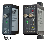
CMCP525 Acceleration
Transmitter/Monitor
Transmitter/Monitor
- Accelerometer Input
- Acceleration Output(g’s)
- RMS or Peak Detection
- 100mV/g Input Std.
- 4-20 mA Output
- 2 Buffered Outputs
- 5 Selectable Ranges
- Fault (OK) Detection
- CSA & UL C1,D2
- DIN Rail Mount
- Optional HP & LP Filters
CMCP530 Velocity
Transmitter/Monitor
Transmitter/Monitor
- Accelerometer Input
- Velocity Output
- Transmitter or Monitor
- RMS or Peak Detection
- 100 mV/g Input Std.
- 4-20 mA Outputs
- 2 Buffered Outputs
- 5 Selectable Ranges
- Fault (OK) Detection
- CSA & UL C1, D2
- DIN Rail Mount
- Optional HP & LP Filters
CMCP535 Displacement
Transmitter/Monitor
Transmitter/Monitor
- Velocity Input
- Displacement Output
- Transmitter or Monitor
- Peak Detection
- 100 mV/in/sec Input
- 4-20 mA Output
- 2 Buffered Outputs
- 5 Selectable Ranges
- Fault (OK) Detection
- CSA & UL C1, D2
- DIN Rail Mount
- Optional HP & LP Filters
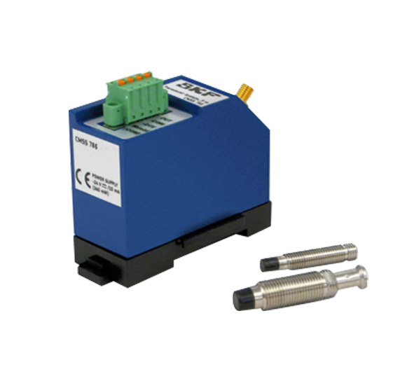
CMSS 785 Series
SKF CMSS 785 System
와전류 형태의 비접촉 변위 / 진동 시스템
Features
- 5mm & 8mm System
- Measurement range : 0.25 to 2.25mm
- Scale factor : 7.87V/mm(200mV/mil)
- Maximal output voltage : -23Vdc
- API standard 670
- CE compliant
- Intrinsically safe(CSA and ATEX)
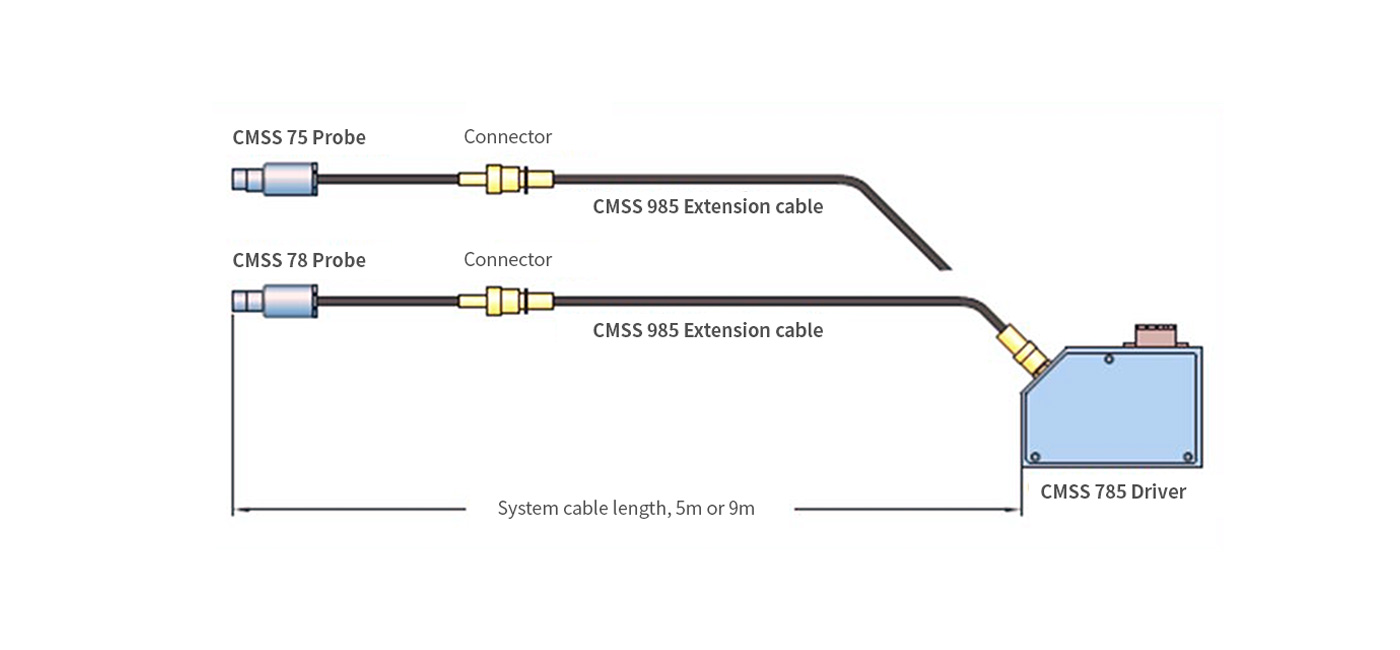
Configuration
Introduction
Using detailed knowledge acquired from many years of supplying high quality sensorsto a broad
spectrum of industry uses, VMS offers rugged connector cable for use with vibration transducersin the Pulp and Paper,
Petrochemical, Steel, Mining and Construction, Metal Working and Machine Tool Industries.
The weakest part of any vibration monitoring system is the sensor and field cabling.
Selection of a quality sensor is the first importantstep towardsthe integrity of a system, but equally importantis the choice of mating connector cable.
Features
- For use with the VMS range of vibration sensors
- Rugged and cost-effective
- Shielding for low-voltage dynamic vibration signals
- Proven design
- Isolated cable
- IP 65 type for economical choice and suits applicationsin lighter industrial environments
- IP68 type allow no ingress of dust and are suitable for continuousimmersion in water
Description
VMRS connector cable is designed for use with piezoelectric vibration sensors which require high specification shielded cable to maximize the quality of the signal transmitted to the monitoring system.
VMRS connector cable consists of a shielded twisted pair cable (with or without armor) integral with a connector made of high quality engineering plastic and sealed (IP65).
VMRS connector cable also provide IP68 type connector: an assembly with a twist lock and an assembly with a locking collar.
The locking collar is a threaded connector that threads onto an accompanying sensor adapter.
It is recommended to secure the sensor adapter to the accelerometer connector using thread lock(Loctite).
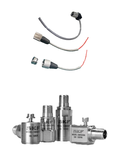
VMS’s IP65, IP68 VMRS Connector Cable (top),
and vibration sensors (lowest).
and vibration sensors (lowest).
Specifications
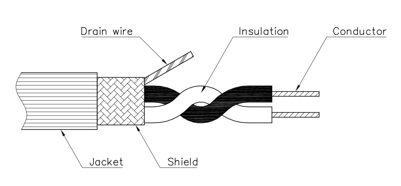
Signal Cables
Two insulated conductors are cabled together with one uninsulated drain wire and two glass cord filters.
| VMRS 0210-N-1P | For general applications | VMRS 0220-N-1P | For high temperature applications | VMRS 0295-M-1P | For Marine applications |
|---|---|---|---|---|---|
| Conductors | Tinned plated copper, Typ. 0.5 mm | Conductors | Tin plated copper, Typ. 0.25 mm2 | Conductors | Tin plated copper, Typ. 0.75 mm2 |
| Color code |
· Power/Signal : Red · Common : Black · Outer Jacket : Blue |
Color code |
· Power/Signal : Red · Common : Black · Outer Jacket : Red |
Color code |
· Power/Signal : 1A (White) · Common : 1B (White) · Outer Jacket : Black |
| Outer Jacket Diameter | Typ. 5.9 mm | Outer Jacket Diameter | Typ. 3 mm | Outer Jacket Diameter | Typ. 6.8 mm |
| Wire Materials | All conductors, drain wires are of tin plated copper | Wire Materials | All conductors, drain wires are of tin plated copper | Wire Materials | All conductors, drain wires are of tin plated copper |
| Jacket material | Urethane | Jacket material | Teflon | Jacket material | Polyolefin |
| Capacitance | Typ. 75 pF/m | Capacitance | Typ. 75 pF/m | Capacitance | Typ. 100 pF/m |
| Resistance | Typ. 0.0349 ohm/m | Resistance | Typ. 0.0392 ohm/m | Resistance | 0.026 ohm/m |
| Voltage Rating | 30V RMS | Voltage Rating | 30V RMS | Voltage Rating | 250V RMS |
| Working Temperature | -30℃ ~ 80℃ | Working Temperature | -30℃ ~ 200℃ | Working Temperature | -30℃ ~90℃ |
| Heat and flame resistance | Non-flame propagating | Heat and flame resistance | Non-flame propagating | Heat and flame resistance | Non-flame propagating |
| Meets ROHS requirement | Meets ROHS requirement | Meets ROHS requirement | |||
| Class certification | ABS, BV, RINA, DNV, GL, KR, LR, NK, CCS | ||||
| Halogen free compound (SHF1) |

Fig 8. Connector Wiring Diagram
Installation considerations
Isolated cable
Within a single-shielded cable/connector assembly, “isolated” meansthe drain wire (and hence the shield) are NOT connected to the sensor.
Drain-wire (shield) must be connected to ground at the instrument.
Silicon grease
When assembling any cable/connectorto the vibration sensor, application of a small amount of silicon grease to the pin-contactsis recommended to ensure reliable operation over a long period.
Sensor installation kits available from VMS include the appropriate silicone grease.
Connector designs
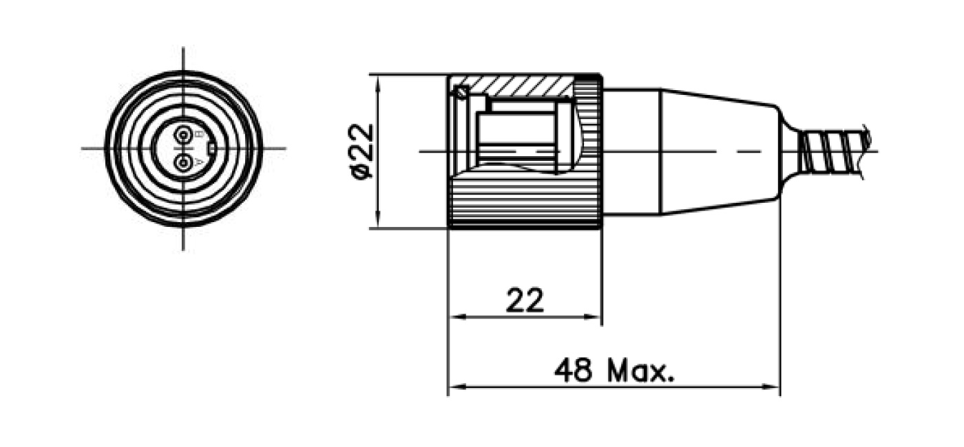
Fig 1. IP65, Straight Connector, MIL-C-5015Female
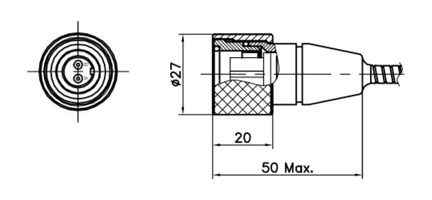
Fig 2. IP68, Straight Connector MIL-C-5015 Female
Cable assemblies
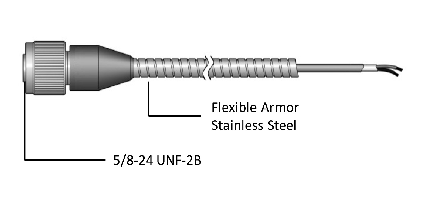
Fig. 3.
Straight Type, MIL-C-5015Female
Straight Type, MIL-C-5015Female
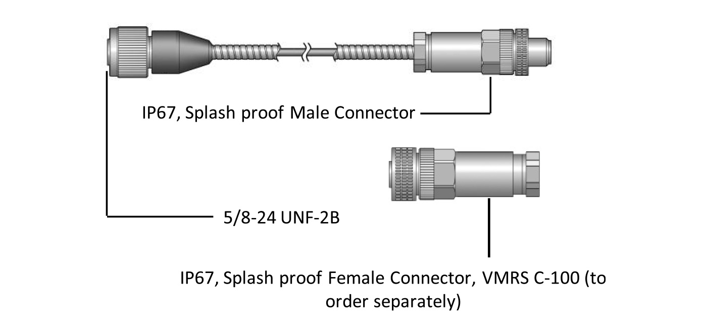
Fig 4.
Straight Type, MIL-C-5015, Female
Straight Type, MIL-C-5015, Female
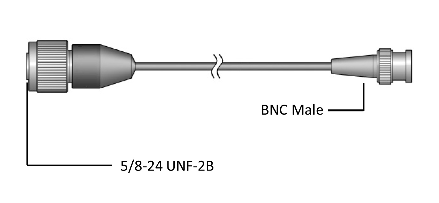
Fig 5.
MIL-C-5015Female & BNC-Male
MIL-C-5015Female & BNC-Male
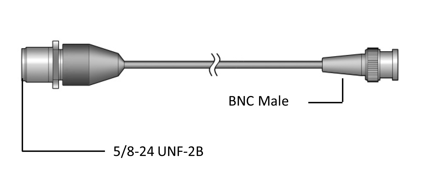
Fig 6.
MIL-C5015Male & BNC-Male
MIL-C5015Male & BNC-Male
Ordering information
VMRS
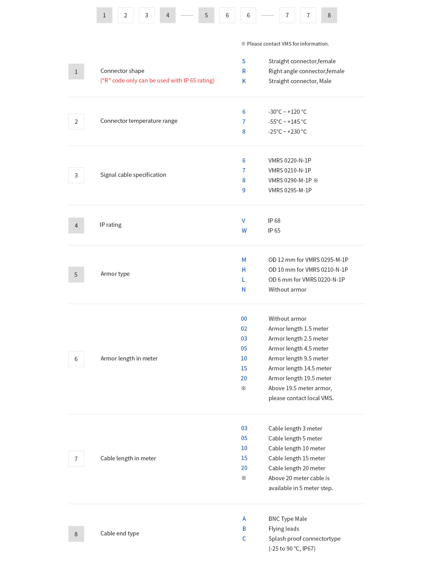
Example

Product Support Plan (PSP)
A range of Product Support Plans is available to protect your investment. Contact your local VMS sales representative for additional information.
Installation and training
Installation and training available through your local VMS supplier or representative.